Onboarding Exercise 2 – CAD Quoting
The TransMagic eval gives you a host of tools useful for quoting and estimating customer work. You can view and measure parts and assemblies, dimension, generate bounding boxes, mass properties, surface area and edge length, as well as create annotations, saved views and markup.
Save standard and PMI geometry out to 3D PDF for non-CAD users, and be sure to check out the video on How to Create a Technical Data Package, at the bottom of this article – the ultimate 3D PDF which can hold all your CAD data and associated files.
In the video embedded below, the following subjects are covered (see time stamp at end).
- Assembly Browser (0:24)
- Some Buttons Require Selected Objects (0:38)
- Display Bounding Box (0:53)
- Select Bodies (1:44)
- Surface Area Calculation (1:52)
- Mass Properties (2:13)
- Change Materials (2:37)
- Center of Mass (3:06)
- Edge Length Calculation (3:34)
- Saving Views (4:00)
- Section Planes (4:22)
- Orientation Front (5:32)
- Split Views, Orientations (6:00)
- Change Background Color (6:34)
- Dynamic Dimensions (6:53)
- Add Dims to View (8:16)
- Change Color (8:30)
- Transparency (8:44)
- Render Modes (8:52)
- Stitching Surfaces (9:27)
- Annotations (10:17)
- Markup (10:32)
- Copy Image (10:53)
- Turn PMI On/Off (10:26)
- Select PMI (11:38)
- PMI Views (12:00)
- Export PMI to 3D PDF (12:23)
- Working with 3D PDF (12:40)
Scroll down further for specific notes related to this video.
Notes
Here are a few additional notes which may be of help when evaluating TransMagic.
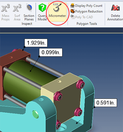 Micrometer
In addition to the tools shown in the video, all core TransMagic products include the Micrometer tool. Use it by clicking on any solid geometry; micrometer determines the part thickness at the point you click, perpendicular to the clicked surface.
As with any unit measurements, if you want to change units, click on the Settings gear in the upper left corner of the screen, and change your units in the General tab.
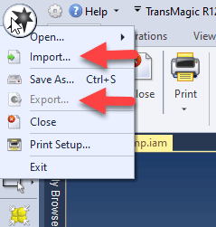 Import and Export
You can import geometry into an existing file, and export geometry out of an assembly or multi-body part. The Import and Export buttons are positioned under the TransMagic icon in the upper-left hand corner of the screen area. Note that in the screenshot at right, ‘Export’ is disabled; this is because you need to tell Export what specific geometry you want to export by pre-selecting it. See section on pre-selection below.
Pre-Selecting Geometry Enables Some Buttons
Although it’s mentioned in both lessons 1 and 2, it bears repeating that some buttons require that geometry be selected in order to be enabled. This is demonstrated at 0:38.
To Test-Drive Transmagic
If you or someone you know would like to test drive TransMagic, here’s the link.
To Return to the Onboarding Main Page
To return to the main onboarding page, click here.