The Red Light and Error Feedback
Note: This is the second article on Diagnostic Tools for CAD Files. This article focuses on what happens when you use the Auto Repair Wizard to repair a model and get the ‘red light’. Click here to access the first post in this series, Diagnostic Tools for CAD Files Part 1.
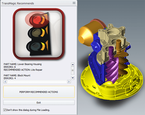
Figure 1 – Auto Repair Wizard and Model in TransMagic
Whereas the yellow light indicates open circuits where geometry is missing, the red light indicates more extreme problems such as bad vertices, bad edges, or self-intersections. Some of these problems can be fixed with Lite Repair, and some require Full Repair. Let’s look at a specific example (see figure 1). This SAT file has problems that warrant the red light. Along with the red light you will get feedback on what specifically is wrong with the file. Here, two bodies have errors; Lower Bearing Housing has 8 errors, and Block Mount has 4 errors. Note that the problematic part or body is highlighted yellow as well, making it clear where the problem lies. In this case, all 12 errors should be resolved when we use Lite Repair, which is included in all TransMagic products.
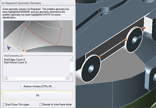
Figure 2 – Bad Geometry List
If we were to click on ‘Perform Recommended Actions’, the ARW would make the repairs and give us the green light. But if we want to do some further diagnosis (perhaps we want to know where the problems are), we can instead click on ‘Exit’. ‘Exit’ will disregard any planned repairs and instead bring up a dialog that indicates what Un-Repaired Geometry Remains (see figure 2).
Highlighting the Problem Areas: The ‘Un-Repaired Geomery Remains’ dialogue will count the total number of bad elements (see the Bad Geometry List at left) and highlight the bad geometry on the model (see areas highlighted orange at right). As the dialogue explains, areas highlighted orange are problematic, and any attached geometry is highlighted white for easier identification.
Bad Edges: When we see ‘Bad Edges’, it means that the edges for the geometry do not match the surfaces that they are edges for; as long as these edges are within a certain tolerance, TransMagic Lite Repair will disregard the bad edge and create a new accurate edge based on where the two surfaces intersect.
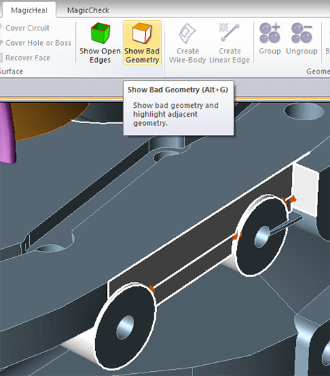
Figure 3 – Show Bad Geometry
The same thing happens with a bad vertex; normally a vertex should be the point at which two or more edges meet. Sometimes the vertex gets moved as a result of an error in the CAD system or a problem during translation. In this case, TransMagic Lite Repair can analyze where the edges actually do meet, and move the vertex to that location. Essentially, Lite Repair is not changing the geometry at all, just snapping key edges or vertices to where they belong, given the surrounding geometry – actually this is correcting the model to conform to proper structural integrity.
Another way to access this same graphical diagnostic information is by simply clicking the Show Bad Geometry button which is a part of the MagicHeal toolbar (see figure 3). Note that in the figure at right, the bad vertices are colored orange, whereas surrounding edges, affected by the bad vertices, are colored in white. This color combination, orange for problem geometry, and white for surrounding/affected geometry, can help the user to quickly spot problem areas.
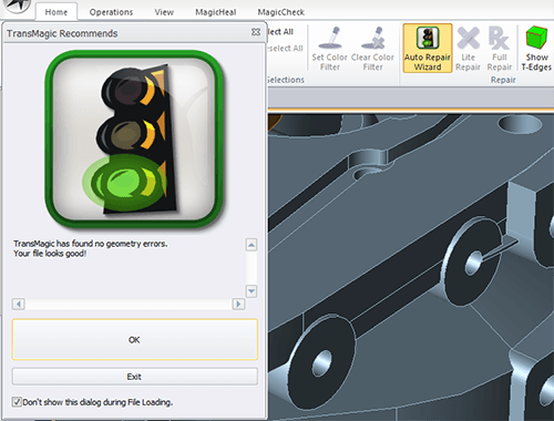
Figure 4 – Green Light, Error Fixed
If you do click OK when prompted by the ARW, TransMagic will attempt the repair; if the repair is successful, you will automatically get the green light, which indicates that the file is now a watertight solid model (see figure 4).
There is yet more to say about using TransMagic to diagnose CAD files, so check back in a week or two for the next segment!