 How do you choose the best CAD file format for any given situation? The CAD Format Ladder can help you optimize data exchange with your customer or supplier.
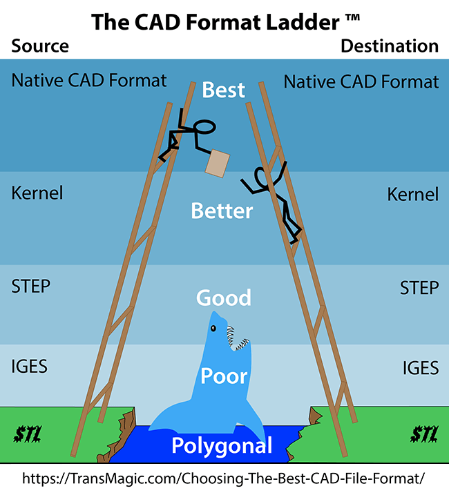
At TransMagic we deal with thousands of CAD file translation and repair issues every year. These issues can be minimized by using this rule of thumb:
“When sending out CAD data, or receiving CAD data, go as high up on the CAD format ladder as possible.”
Your best results will come from requesting a CAD format that is as high-up on the format ladder as they can give you. You’ll also want to send data back to your customer in a format that is as high-up on the ladder as you can write.
The higher you go on the format ladder, the better quality the data is, and conversely, the lowest point you go on the format ladder becomes the weakest link in the file exchange.
Native CAD Formats
Native CAD formats are the default formats written by any given CAD system. For example, CATIA uses CATPart and CATProduct, and SOLIDWORKS uses sldprt and sldasm as their native formats. Here’s a list of native, geometric modeling kernel and neutral CAD formats.
Geometric Modeling Kernel Formats
All CAD systems also have a geometric modeling kernel which underlies the native format, and allows the creation and manipulation of geometry. CATIA uses the Convergence Geometric Modeler (CGM), Creo uses Granite (g) and both Siemens NX and SOLIDWORKS use the Parasolid kernel (x_t).
The geometric modeling kernel is exactly the same as the native format in terms of pure geometry, since the native format for any given CAD system is based on the its geometric modeling kernel. You can’t get any better geometric fidelity than the kernel format as long as you are using the kernel for the source or destination application. For example, if you have a CATIA part and you want to open it in MasterCam, save it to the Parasolid kernel format since that is what the MasterCam software application is based upon.
Neutral CAD Formats
STEP
STEP, which stands for the Standard for the Exchange of Product Model Data, can work with every major 3D CAD system, but in spite of this versatility, STEP rarely outperforms Native-to-Native or Native-to-Kernel CAD translation strategies. The quality of your STEP translator is the key factor; all STEP translators were not created equal. Importantly, this refers not only to the translator that wrote the STEP file, but the translator that will read the STEP file into your native CAD system. Poorly written STEP translators have two opportunities to mangle your data; on the way out, and on the way in.
Many STEP translators take the shortcut of translating all data to splines, which is the fastest, simplest way to capture geometric data; unfortunately, splines are not as precise as analytic geometry.
IGES
IGES, or the Initial Graphics Exchange Specification, is another neutral CAD format that can be read and written by many CAD systems, but is in fact the worst possible alternative. IGES has not seen any development since 1996, over twenty years ago. One of the problems with IGES is files are almost always surfaces; if you do have to work with IGES files, make sure you have a model repair tool that can stitch together surfaces, remove artifacts, and extend and re-intersect surface edges to give you the best chance at producing a watertight solid model. Another problem with IGES is that most IGES translators are not well written, so you’re not only dealing with surface data, but poorly defined surface data at that.
IGES Solids – There is an implementation of IGES which actually supports solid models. This is called Manifold Solid Boundary Representation Object, (MSBO), but it is not widely used; for MSBO to produce reliable and precise translations, it has to be used to both write and read the IGES file.
Polygonal Models
Polygonal models are included at the bottom of the CAD Format Ladder because though they are often confused with CAD models, but are not as accurate or information-rich as CAD models. CAD models are sometimes referred to as ‘precise’ or Boundary Representation (Brep) models, and polygonal models can be referred to as ‘tessellated’ or Visual Representation (Visrep) models, because they are composed of triangles. Typical polygonal formats include Stereolithography (STL), Obj, 3D PDF and Web GL. Polygonal formats are useful for visualizing large assemblies because they are more lightweight than CAD geometry. You can read more about Brep vs Visrep models here.
The Goal is Quality CAD Geometry and Complete CAD Metadata
The goal of the translation should be to generate the best geometry possible with the most complete CAD metadata. In terms of geometry, watertight solids with analytic geometry are preferred. CAD metadata can include Product Manufacturing Information (PMI) attached to the model, User Defined Attributes (UDA) which can carry design or manufacturing information, and format-specific data such as CATIA’s Publication Data, which can also carry design and manufacturing information. Less than optimal geometry or missing metadata can lead to loss of design intent, time consuming model repairs, inaccurate quotes and manufacturing errors.
Solids are Preferable to Surfaces
One benefit of watertight solids is that they are read as a single part which is easy to edit in all major 3D CAD systems. Conversely, surface geometry imports into CAD applications as hundreds or even thousands of disconnected surfaces; until the surfaces are repaired or stitched together, they are not of much practical value.
Eliminating Bad Geometry
Non-watertight CAD geometry can have sliver faces, zero-area faces, bad edges and vertices, inverted vertices and duplicate vertices. These artifacts can make translation into your CAD system difficult, as well as hindering downstream applications such as feature recognition, machining, and Finite Element Analysis (FEA). Choosing the right CAD format, and using repair tools when necessary can eliminate or minimize bad geometry.
Spline vs Analytic Geometry
Spline edges and faces are typical in geometry translated from IGES or STEP, depending on the STEP or IGES translator. Splines are a shortcut to approximate geometry; a more precise representation is achieved by analytic geometry which consists of lines, arcs, planes and cylinders. Analytic geometry is better understood by downstream CAD applications; for example, Computer Numerical Control (CNC) systems can readily recognize a cylinder as a hole, but spline geometry may not be recognized. Native and kernel formats use analytic geometry when possible, and repair tools can convert some spline geometry to analytic geometry when it meets mathematical conditions.
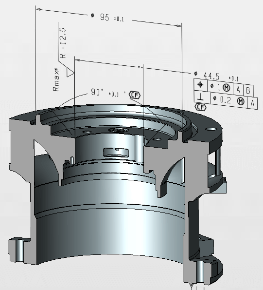 PMI – Product and Manufacturing Information
PMI defines machining tolerances, dimensions and notes which are attached to the solid model. PMI is a major component of Model Based Design (MBD), where the manufacturing data is attached to the 3D model, rather than held separately in a 2D drawing. With the traditional method of 3D model associated with 2D drawings, there was always the risk that the 2D and 3D associated models could become out of sync. Storing the data with the 3D model makes it easier to see where each dimension and note attach to the model, and offers non-ambiguous design information.
PMI is primarily composed of Geometric Dimensioning and Tolerancing (GD&T) information, a well-accepted standard across all industry sectors which helps machinists and other manufacturing personnel understand the required tolerances.
If PMI is missing or inaccurate, the required tolerances are not communicated, which could lead to defective parts being manufactured and increased scrap. It’s important to be able to view PMI and translate the PMI to other formats for the benefit of customers and trading partners. Formats which will support PMI include most CAD formats, as well as 3D PDF and Web GL.
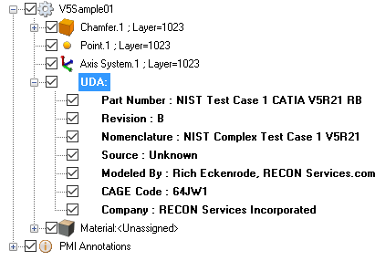 UDA (User Defined Attributes)
UDA can be any textual data the originating organization will define in order to correctly identify the part or assembly. In the example at right, UDA includes part number, revision, naming conventions, source, author, cage code and company.
Not all translators will translate UDA data. Check to see if UDA exists on the translated file, and if it doesn’t, check with the original author to see if UDA should exist.
 Versions
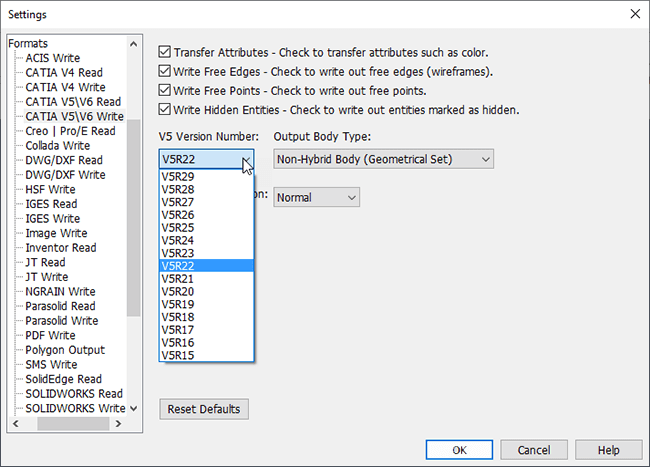
The format you use is imporant, but so is the version of the CAD format.
If you send a trading partner the latest version of a CAD format, they might not be able to open it if their CAD system or translator cannot read that version.
Quality CAD translation tools have version settings available for compatibility tuning. In Figure 4 you can see that CATIA can be written to versions V5R15 through V5R29, but the default is V5R22. Defaulting to a version which has been available for a few years helps with file compatibility between trading partners.
 Settings
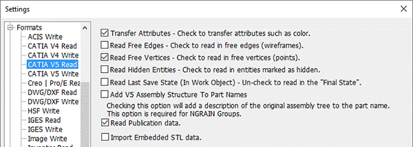
Settings for each format can be critical. Though the default settings are optimized to work well in most situations, taking the time to tune the read and write settings for specific situations can significantly impact the usability of CAD model translation for the customer or supplier.
Looking at the example for CATIA V5 Read (Figure 5) for example, should Read Free Edges be turned on or off? How about Read Hidden Entities taking the time to understand the best format, version, and settings for each read and write situation will greatly increase your chances of being able to share quality data with your supplier or customer.
Testing for Functionality and Quality
Testing and comparing results between translators is often the only way to know the best format for a situation. Over the years we have found that the CAD Format Ladder works well, but there are sometimes exceptions; for example, when a customer is using a legacy CAD application which can only read IGES geometry. Testing with real-world CAD data is necessary to ensure the best possible CAD model data for your customer or supplier.
More Formats Equals Increased Power and Flexibility
TransMagic’s tools give you access to native, kernel and neutral CAD formats, so that you can read or write the best format for each situation. If your customer uses CATIA, get the native format from them, and send them back the native format. If your customer uses NX, read their native NX geometry and send them JT or Parasolid geometry. With more formats at your fingertips, you have more opportunity to expand your customer base, capture additional industries and grow your business.
Even if you already have the capability to read native CAD formats, you may be experiencing poor translations; not all CAD translators are created equal. Considering the immense amount of design and engineering time wasted through customer communications, model repair and remodeling, it makes good business sense to evaluate other solutions.
Conclusion
Choosing the best CAD file format is made easy by using the CAD Format Ladder. You should ideally be able to open any native CAD format, and write to either native, geometric modeling kernel, or STEP formats, in that order of preference. This strategy will ensure the best possible CAD model data is being translated, and minimize time spent repairing CAD model geometry.
If your current solution does not give you access to the best possible native CAD formats, or you are unable to write to the formats you need access to, try TransMagic SUPERVIEW, PRO or EXPERT. SUPERVIEW can read all major 3D CAD formats, PRO adds the ability to write to STEP, IGES and kernel formats, and EXPERT adds the ability to write to native CAD formats such as CATIA, AutoCad, JT and SOLIDWORKS.
The TransMagic evaluation is available at https://TransMagic.com. If you’d like to discuss your needs with an account representative, contact us at 303-460-1406 Ext. 615.
Related Articles
To see all the formats TransMagic can open and write to, visit our CAD Formats page.
To take advantage of Geometric Modeling Kernels, it helps to know which kernels underlie which CAD applications; here’s a helpful listing. Which Geometric Modeling Kernel?
Production bottlenecks can affect slow down your design and engineering process before you even get to the factory floor. Do You Have These Production Bottlenecks?
Why is IGES at the bottom of the list? Read more about IGES in these posts; IGES, IGES vs STEP.